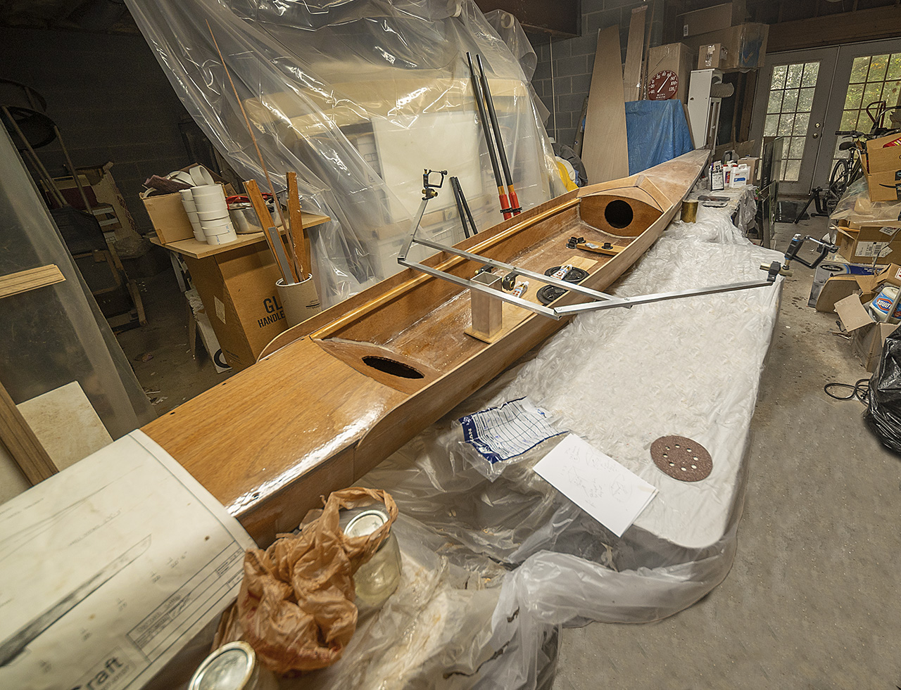
While waiting for the epoxy behind the first side rail to set, I made a sudden executive decision: maybe I’ll eventually build the foam composite rigger as shown in the drawings many days ago (start here — it is a tedious journey) but (1) the temperature in the boatyard has fallen back into the middle 60’s where foam will not perform at its best, and (2) I’m still trying to avoid buying more epoxy and hardener which wrapping a foam rigger would surely require, and (3) I would, it seems, prefer not to take up yet another new-to-me technology at this very moment. So the rigger will be made from rectangular aluminum tubing. It will serve as a highly adjustable prototype and require nothing more than drilling and tapping a handful of holes. The metal is on the way. As a rigger, it will not be elegant, but it will work (now, if I were a 6’5″ collegiate contender, I doubt it would be strong enough, but I should be so lucky as to bend something). As a prototype, it ought to be handy.
As for the splashbox, all went reasonably well with the first side panel last night. I used cell-o-fill thickened epoxy to minimize drips (it should have been even thicker). I propped the rail against the boomerang near its final position on the foredeck then raised it until it was near its final position all along the gunwale. I clamped it near the foredeck (I should have put epoxy behind it then and there, but, I managed). I painted the lower inch of the side rail where I could get to it with epoxy and clamped it near the after deck and around the middle of the office. At that point, I dared pull it away from the forward part of the gunwale far enough to get epoxy behind it there, too. I drizzled more epoxy over the top edge of the joint, letting it self-level into a small fillet, cleaned it up with a stick and my fingers dipped in alcohol, and finished with a small fillet on the boomerang. I placed PVC clamps every 8-10 inches. I clamped the rear-most portion of this first side rail with a long clamp reaching all the way across the boat. I tended drips with an alcohol-soaked paper towel for half an hour or so. And then I left it for the night. It looks good this morning, solid and neat enough.
The second side panel went on much more quickly than the first. Experience counts. I could not for the life of me figure out how to put the wood under the miter saw to get the angles right where it meets the boomerang. So I cut a simple angle there and then used 80-grit on the orbital sander to make quick work of the miter across the 6mm thickness. I made an especially thick epoxy mix to apply between the panel and the hull. This time it did not drip, but it also did not flow so neatly when applied on top of the joint. I had to encourage it to smooth out and spread there with an alcohol-dampened finger. Then I locked the second side rail in place with usual slew of metal and PVC clamps. When I removed the clamps, the boat finally looked like an unfinished shell rather than like a very thin unfinished boat.
Day 69
wood-flour fillet to level on the right.
I used a Japanese finishing saw to trim the ends of the boomerang to match the outside edge of the side panels. The cut only needed the slightest touch with 120 sandpaper to leave everything flush. There’ll be a beauty pass (or two) for the hull before all is declared lake-worthy, so any remaining roughness will be dealt with then.
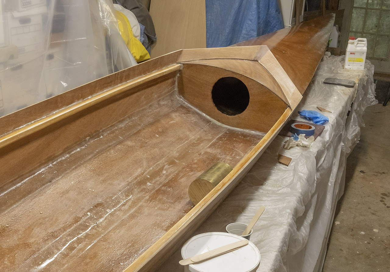
Still to go for the splashbox: fill the the gaps where the box meets the foredeck (I oughta shoulda mounted the boomerang an inch or two farther forward. The plans showed that, a close look at the renders at the head of the “building a boat” page will show that. Oh, well: live and fix.) The resulting gaps are an annoyance upon which my attention is so focused that it feels like a crisis. A determinedly objective evaluation says that wood-thickened epoxy will easily fix that mess. I cite here the near-universal, oft-repeated, and variously phrased advice from the Chesapeake Light Craft builders’ forum: “Just build the boat. You can fix just about anything if it’s for show or if it bugs you enough, but first, get it on the water.”
Some vanity is nevertheless permitted. I hated the look of the cell-o-fill fillets so I poured 30g of wood-flour thickened epoxy over each (think cold syrup or warm molasses, not peanut butter). Gravity is your friend. The bigger fillets around the bulkheads may meet a similar fate.
I like this NASA / JPL gravity-assist stuff. Maybe I can do something similar for filling the gaps in the splashbox and for the fillets below the boomerang. I said “maybe,” OK?
I’ve been haunted by the prospect of running low on epoxy at the last minute, and when I went to MAS Epoxies this afternoon I discovered that after clearance sales, promos, a coupon, and my loyalty points, I could buy a quart of finishing marine resin and the proper hardener for just about half price, so I did. MAS urges that this is less a structural than a surface-building resin so I’ll use what I have on hand for the few remaining structural tasks and wait to do more surface work until the new goop arrives. That will leave plenty of time for preparation.
I aim to take one more cut at getting a smooth coat on the decks, and if that fails, then satin or matte it is. And I need to sand, fill, and otherwise finish the hull surfaces, probably with a long board. And make the propulsion kit and get that mounted. I don’t know exactly what the order of march will be, but there aren’t that many steps remaining between this boat and the water.
Current cogitations: various means of mounting the seat, 4″ velcro for stretchers, Dobsonian-derived sling for heel clips, a bungee rather than tilt for easing the recovery. Rustoleum flat black automotive acrylic works great on the sculls. It also looks good for the small accents at the bow, but don’t let acetone anywhere near it. Acetone removes the acrylic even after several days of curing. Your first hypothesis about how I might have found that out will be correct.
Day 70
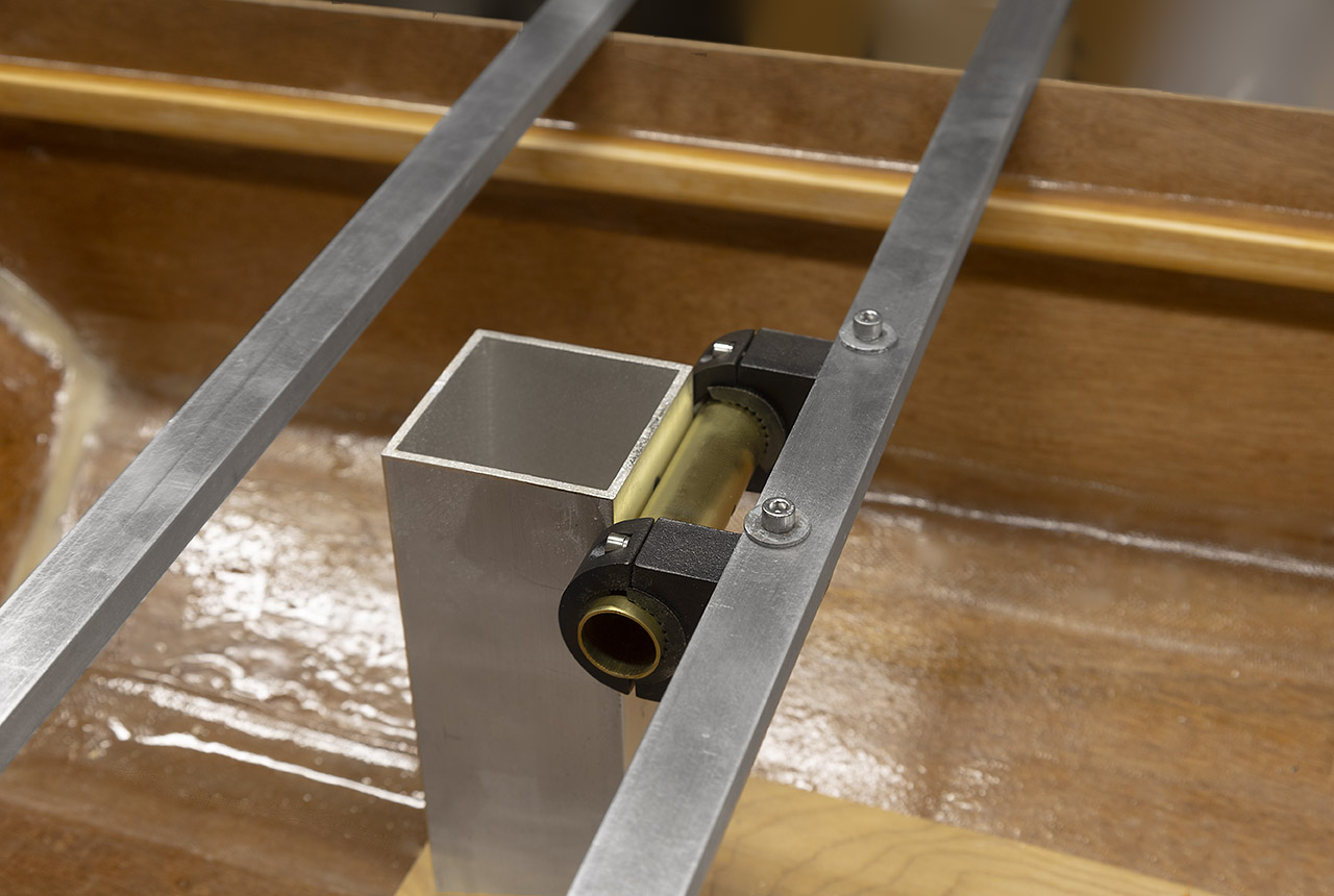
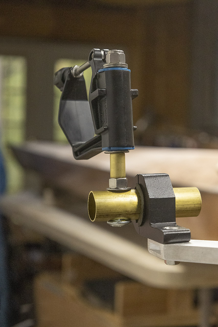
I laid out and drilled the major connections for the aluminum rigger, more or less in line with the drawing up above. I put 5/16 holes through both sides of the angled arms where they intersect the horizontal bars. Then I center-punched the metal below and drilled 3/16 holes all the way through the lower tubes. Those I threaded as if the rectangular tubes were solid metal. I installed 1-inch 1/4-20 stainless steel flat head socket bolts flush with the surface of (3). Seems light and rigid, but what do I know? Here’s a schematic of the left side of the rigger.
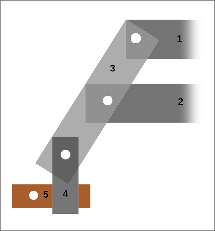
Note that in trimming (3) to size, the distance between left and right (4) blocks should be a bit less than the nominal spread of 160cm. Maybe 156cm (61 3/8 inches) so that the full range of plausible spreads (said to be from about 158-164cm) would be available. The only spread not available with this schema is the actual distance between the ends of the (4) blocks, so keep that distance safely under the useful range.
Day 71
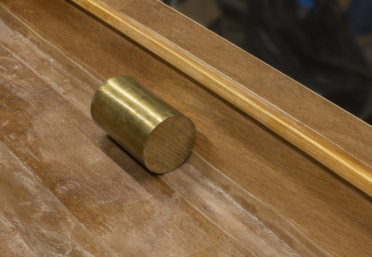
And… done, with the minimum likely spread (158cm) just accessible outside the clamps. The 3.5-inch brass tubes (5) would allow a spread of up to about 170cm, safely beyond any plausible need, so shorten them, move them a little inboard, make another set, or just say fine, too much range is better than not enough and position them where they need to be.
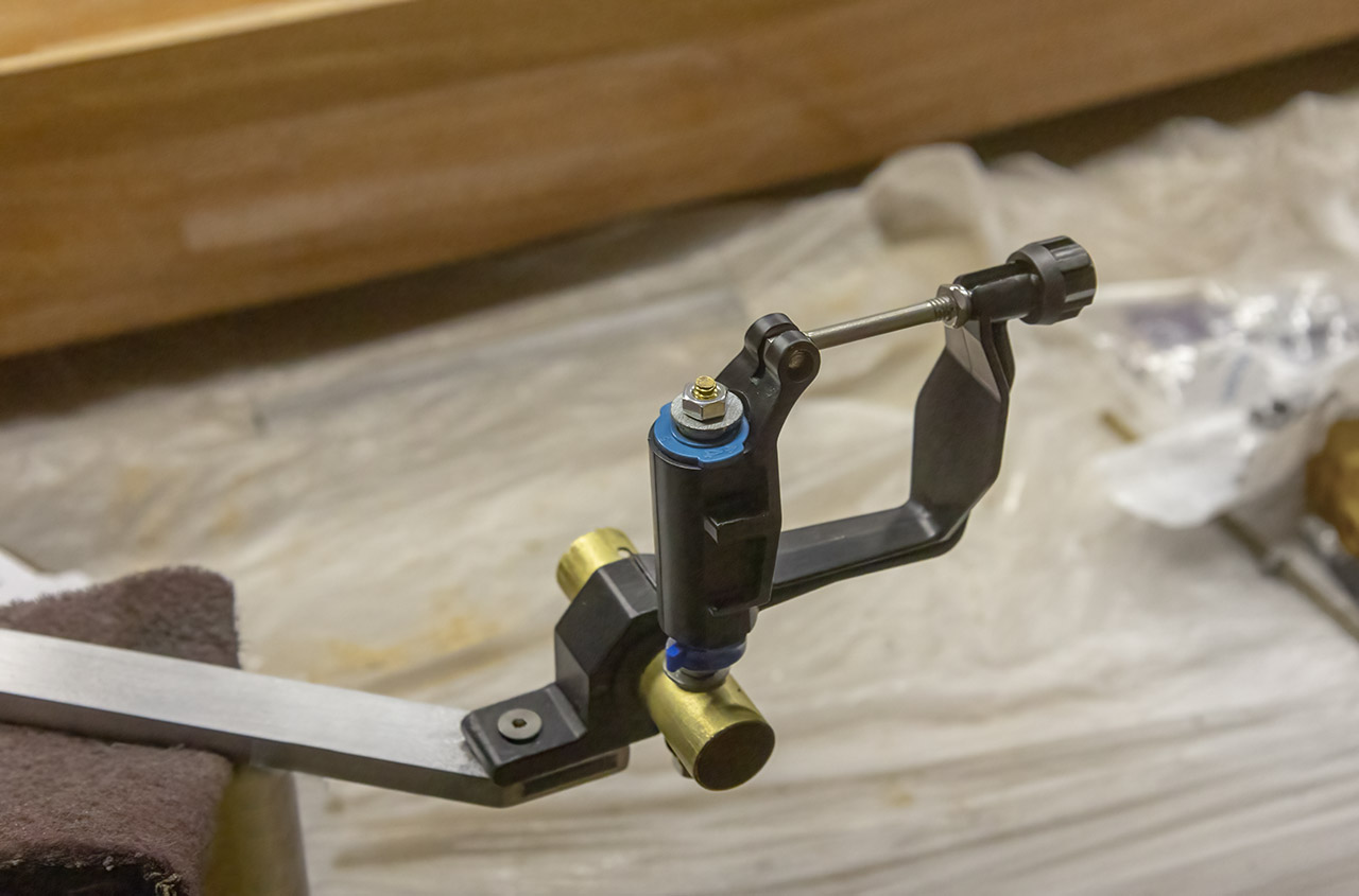
(But flimsy. And shown backward. And on the wrong side of the boat<sigh> Keep reading.)
The oarlock pins went together without major adventure and the oarlocks attached to them easily enough. The 1/4-inch brass cores of the pins look delicate compared to commercial products.
See, given the leverage involved, I think even an old man might strain that.
See below for a fix.
Day 72
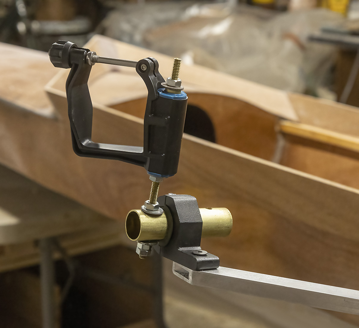
I’ve rebuilt all this around 3/8-inch stainless for oarlock pins and it’s far more robust. I also drilled out the hole through which the light-bar clamp is attached to the strut of the rigger so that the bolt there passes all the way through the strut with room for a hex nut below. I’ll get the ratchet wrench and Loctite out after I’ve gnawed on the current version for a while and not found it obviously flawed. Also, various bits will need to be aligned more critically than they are right now.
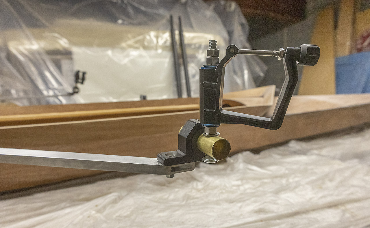
Much more solid. But is there enough difference in height between the two oarlocks to permit the sculls’ handles and sculler’s hands to pass comfortably? It’s probably fine. According to this site:
http://www.merrimackrowing.org/news/95-rigging-your-single-scull
the difference shown here at the pins is just about right. The difference gets amplified by the inboard. If the content at that link is somehow insufficient, then know that the keyword for all this is “crossover.”
Just to keep life interesting, I now find that the universal custom within the sport is left over right. That is, the left hand passes over the right at the crossover. I have the oarlocks set the other way around (about a 5 minute fix which took me 20 because I can’t help messing about with this boat). This means, incidentally, that the cover photo on the home page of this blog needs to be redone. Also, remember that the pin goes toward the bow. I repeatedly figure it out and get it wrong a significant fraction of the time. Maybe I’ll put a bright stripe down the inside of the oarlocks so I can tell at a glance if I’ve got them going the wrong way without being tempted to “figure it out” each time I go churn up the lake. Or I could just learn. Heaven forbid.
And of course now that the rigger is finished, I am rethinking how to attach it to the upright. Because that’s what I do.
Day 73
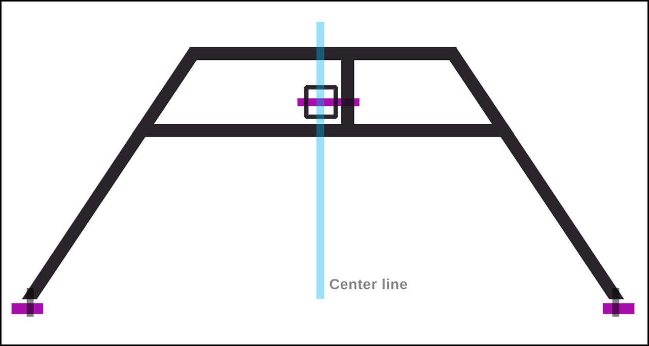
After thinking too long and trying to grasp what adjustments would be needed, precluded, made easy, made hard, what mounting schemes would limit adjustments, customizations, or preserve existing structures after wrong-headed hasty cuts and drilling, I came up with this:
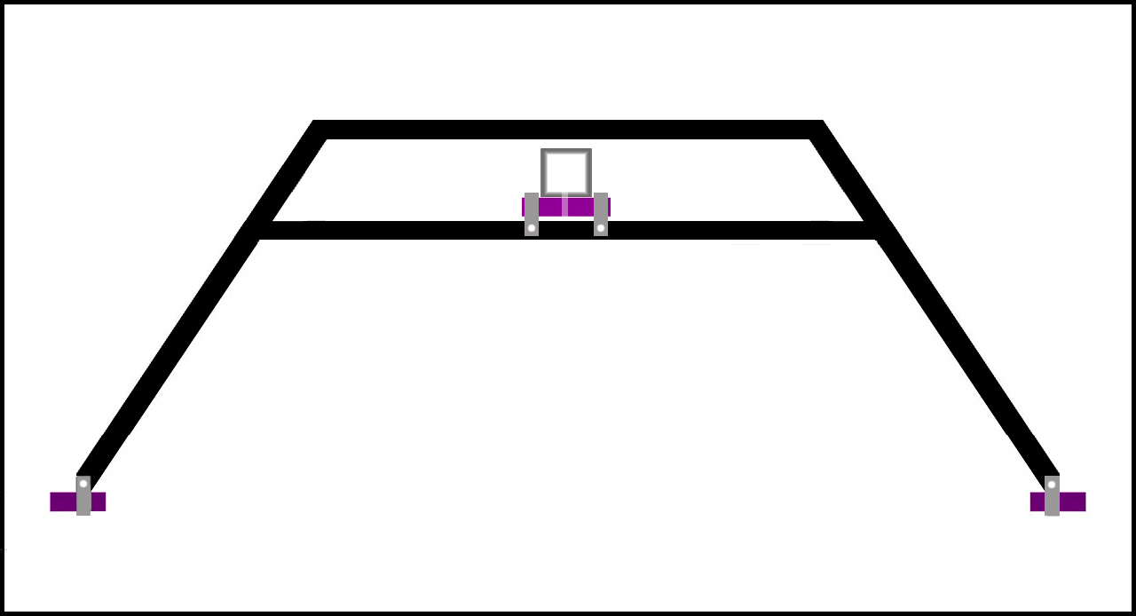
I built that version with only a few miscues along the way. Let’s not dwell on them; they have been erased and made moot. Brass is shown in purple (why not?) and aluminum in grey and black.The square in the center of the “A” crossbar is the cross-section of the slider’s upright. I think it can be much shorter than originally contemplated, but this rigger allows it to be built and adjusted before cutting it down to its proper height. That is, it will allow me to make a lot of mistakes without doing anything too expensive or exasperating.