Overthinking continues and gets a little wild. I haven’t heard anything from RowRigs and have been having dangerous thoughts fed by Internet examples of others who have suffered similar ideas.
Out on the net, plenty of off-the-wall do-it-yourself sliding seats and sliding riggers seem to work and have their fans. Some don’t look particularly finished, but some do. My guess is that a nice sliding rigger could be built in 15-20 hours for less than half the commercial price, and unless I do something truly bizarre to the hull, I can always back out and go with Piantedosi hardware as god and John Harris originally intended.
As of this morning, my thought is to finish the interior (the “stateroom” as they say) as if I were going to install a the standard sliding seat, but instead design and install hardware for a home-brewed sliding rigger instead. Think of the elements needed to mount the commercial solution as a restore-point. As with telescope-building, if I can’t make it precise, I can make it adjustable. In this case, since I don’t know exactly what I need to build, I’ll have to make sure that whatever I end up with is within the range of adjustability of a working design. Individual components — adapters, mounting blocks — can always be reworked. The combination of epoxy and fiberglass has proven to be strong and forgiving. None of this is as complex as some of the astro toys I’ve put together, and as for strength, people build successful composite aircraft in their garages every day of the year. I’m asking for neither the precision of astro bits nor for the strength and failsafe attributes of aircraft bits.
I began by thinking about sliding bearings made from telescoping tubes, but it’s easy to do a lot better than that (they’re sure to bind, and the coefficient of friction between tubes not meant to be used like that has got to be brutal). Some of the productive searches so far: linear bearings, heavy duty drawer slides, sliding seat and rigger dimensions. Links to promising or otherwise useful drawings, reviews, and analyses to come.
Linear bearings were very tempting, but how are they in water? Drylin makes linear bearings said to be suitable even in salt water — for a price. Even if corrosion-resistant, how fast would they wear? Two hundred strokes per mile at five miles per hour is a thousand strokes per hour. Five hours a week for half a year is over 100,000 strokes. What’s their service life? And how much stress will rowing apply to them? It’s one thing to replace linear bearings if they keep your factory running, but replacing expensive parts buried in a rowboat’s innerds would be irksome.
The traditional hack (roller skate wheels running in simple tracks with a retaining scheme of some sort) is said to be noisy, and it always seems to turn out inelegant. I bought skateboard trucks for this a decade ago, but I am less happy with that idea these days.
How about Teflon? Teflon is not especially cheap in long, structural pieces, but take a lesson from telescopes. I could make the track surface a suitable Formica and use Teflon pads or runners on the bottom of the slide. Dobsonian mounts work like that. In them, the goal is “balance.” Stiction and sliding friction are managed so telescopes can be nudged to follow the stars but not drift away in a light breeze or under gravity. Instead, I’d want the least stiction and the lowest coefficient of friction possible (and affordable and durable) for this application. Stiction will not be much of an issue considering the forces involved (nudging a telescope vs hauling for all you’re worth on the end of two nine foot levers), but less is still better. Products to keep in mind: “Optiparts Teflon glide tape,” furniture moving pads, c-channel aluminum.
Gryffyn Rowing offers a more elaborate design than I have in mind. Theirs includes folding riggers rather than a detachable single wing and a reversing gear for forward-seated rowing. Nevertheless, the numbers on their schematic provide excellent starting points:
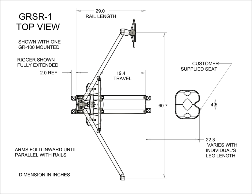
The complexity at the end of the top rigger is one of Gryffyn’s forward rowing gearboxes and its mounting apparatus.
The total length from the back of seat to the front of tracks is 53.3 inches in that drawing. That’s comfortably less than the space available in the shell downstairs. And since the total length “varies with individual’s leg length” my sliding rigger could be at least a couple of inches shorter out of deference to the penguin-plan on which I am laid out. In any event, the seat could be easily moved. Just make sure the tracks are plausible for inseams from, say 26 to 34 inches. If they can be relocated without vast effort to compensate for designed-in stupidity, better. The side view is slightly less reassuring to my uneducated eye (that vertical pillar looks flimsy for rowing loads).
Get close, season to taste, adjust the design as legs, arms, backs, boots, and boats demand.
Day 32
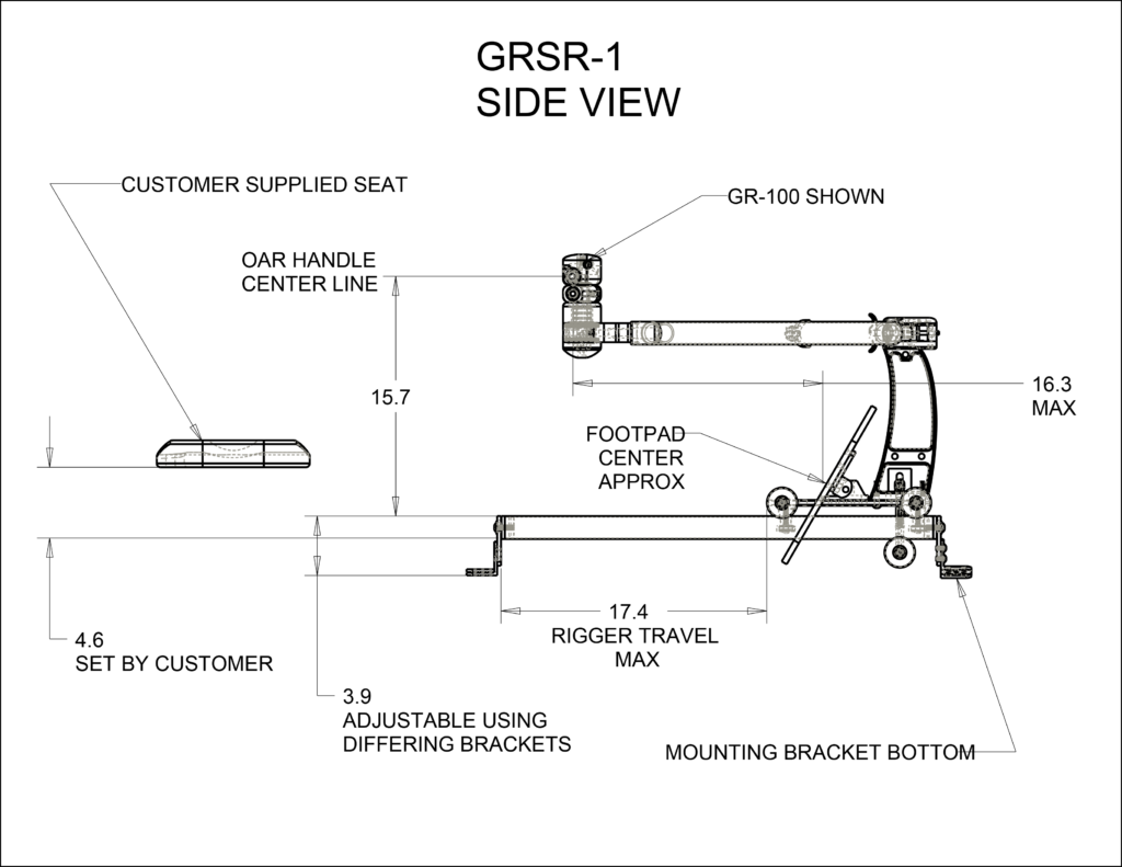
continued along the same lines. I thought I had it all worked out with Teflon and Formica bearing surfaces, using wheels to enforce alignment, and drew it all out to scale (see below). I was busy drawing up a parts list to guestimate costs when I realized that in this schema, every drive would try to tilt the rig toward me, engaging the metal C-channels shown in red which I had intended only to prevent the rig from falling out in the all-too-likely event of a capsize. Look, here’s the trolley under the rigger (Teflon in purple, Formica not shown on top of 1/2×1 aluminum tubes, roller bearings are in blue, all built on and around a quarter-inch thick 8×6 inch aluminum plate):
So, I thought, well, I’ll need to put a low-friction hold-down somewhere to keep the plate from tilting or else arrange an additional Teflon bearing surface at the front of the trolley. If I keep adding surfaces like that, sooner or later, the coefficient of friction is going to catch up. So maybe use a roller or two instead. Then I looked again at the Gryffyn diagram up above and saw that each runner is surrounded by five, count ’em, five wheels. The ones at lower right, beneath the rails, exist to keep the trolley on the track and to prevent it tilting during the drive. In the end, I opted to just forget Teflon experiments and use wheels. It’s a mature sport; you don’t need to re-invent the baseball bat.
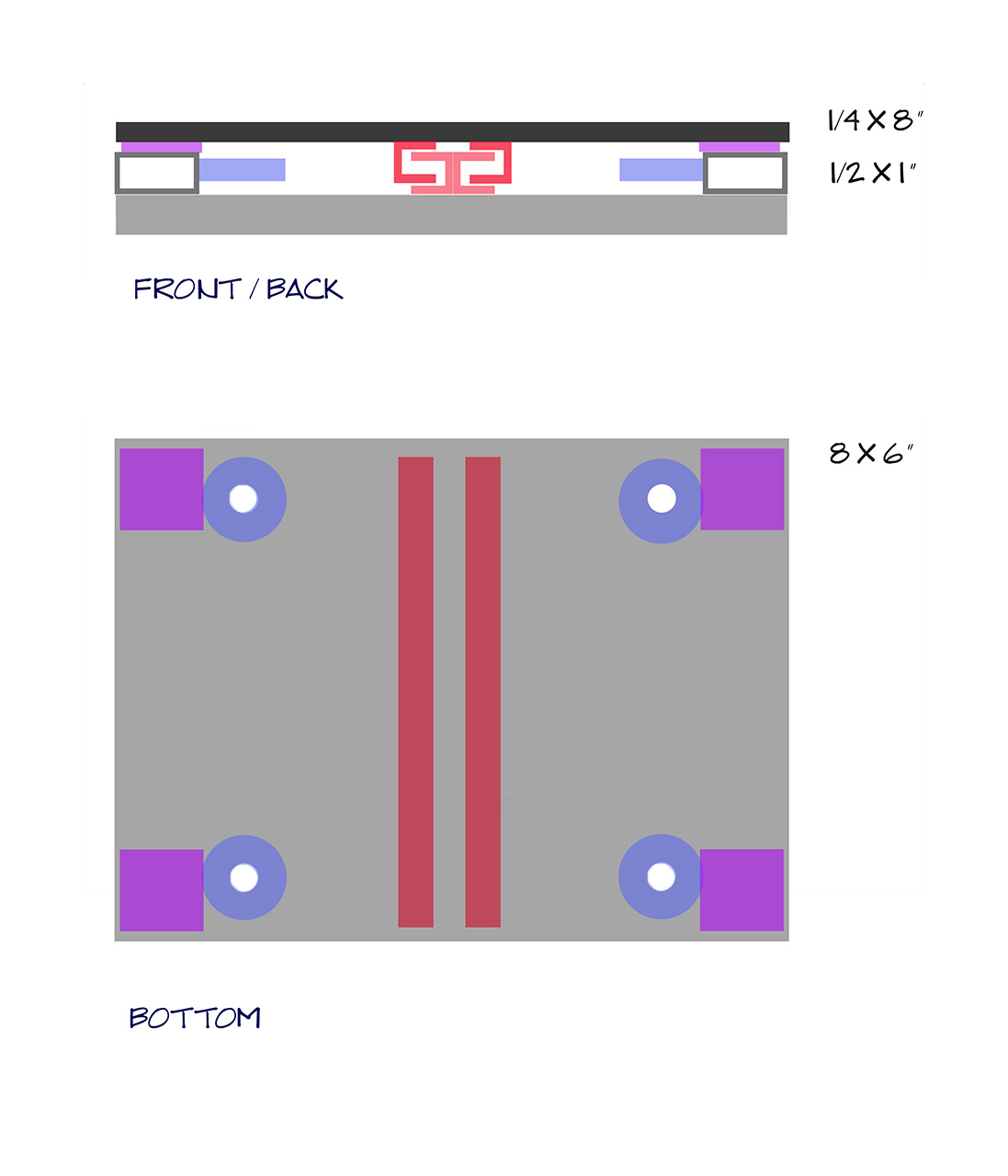
Maybe something like this:
U-groove rollers are mounted on the trolley sandwiching a pair of 1/2-inch tubes which serve as rails. The wheels could be plastic, steel, or what-have-you; the rails are steel, brass, or aluminum and are mounted in wood blocks which are, in turn, mounted to the floor of the boat. These drawings are to scale using 30mm rollers, a 1/4-inch aluminum baseplate as before, two 1/2-inch tubes / rails, and 1×1 inch aluminum tubes provide mounts for the axles / bolts for the rollers. The profile of the rollers is not shown accurately. If the U-groove rollers prove insufficient to keep the trolley on its tracks, then add Teflon along the edge of plate so that it contacts the tubes if things go sideways. Or add a third light-weight guide rail, left, right, or center. Or just make some bumpers to keep things in line. Or anyway, it’ll be fixable. (Virus Boats uses a sliding rigger something like this.)
Can my feet be accommodated in this design? Does it need to be wider? Commerical versions are. The boat has room if the trolley needs to be built around a 6 x 10 or even larger piece. Cutouts in the plate are possible if needed for footspace or to save weight.
The rigger, the “wing” in Row Wing, seems simple by comparison. Oarlocks are not expensive. Pins to hold the oarlocks are. Go figure. Watch some videos on rigging sculls to see what sorts of adjustability and adaptability need to be built into the ends of the rigger. I am not above turning steel bolts into pins — I have a lathe — if I know what they need to do.
Day 33
Holy shit! Holy shit! I tried out the electric planer on some oak flooring clamped in a vice. I love it. I’m going to use it for everything! It will make quick work of planing the sheerclamps down for the decks, but the Chad doctrine must be kept clearly in mind (“You can do a lot of damage with powerful tools”).
Late last night, I also looked at the space available for a stretcher and my feet. And I thought, well, I could use an 8×12 inch sheet of aluminum for the base plate. That’s 2.2 lbs or so. I could drill it out like Swiss cheese to keep the weight down. Or, I could keep using plywood composite. Cheaper, lighter, easier to redo if things go badly; would look great beside brass rails… Let’s do that. And I messed around with the pretty-good skateboard trucks I bought for this purpose 12 years ago. Maybe they’ll do fine. Just work out a track for them and a means to keep them in it. And add a roller to control the tilting moment. Wait. See? It’s happening again: complexity abounds. Still thinking.
Later that same day, what I’m thinking is, “too many parts” and “too much experimentation.” “Too complex.” “Too much reinventing of too many wheels.” And “too many wheels” for that matter. Start again.
How about heavy duty drawer slides? The kind that you mount generators and outdoor kitchens on for RVs. The kind that hold 4 or 5 linear feet of legal papers and are advertised with videos of people opening the drawers and climbing them like ladders. Amazon carries some rated for 170-250 pounds on 20-inch stainless bearings. Build a specialized “single drawer cabinet” on the bottom of the boat and put the slide where the drawer would be. Why is this not worth a try? I think it is worth a try. It seems by far the cheapest and easiest proposed solution yet. But let’s wait a day or two to drop a dime on it.
Drawn (very) approximately to scale, here’s my hull (keel to top of splash box, forward to aft bulkheads) with a simplified version of the Gryffyn sliding rig superimposed as if installed using a drawer slide of 18 or 20 inches. The 17.4 inch rigger travel is the maximum Gryffyn specified; the rigger is shown in two positions that far apart.
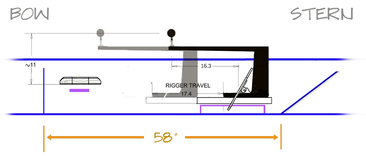
Purple indicates new construction in the boat which should not exceed or preclude what the Piantedosi drop-in would (and might someday) require. The purple block on the left represents a short shelf attached to the side panels (bracing is not shown) to mount a fixed seat. Put this “partial thwart” as low as conceivable since spacers are easy to add. The block under the slide assembly could be approximately as narrow as the Piantedosi rail to leave room for my feet beside it. Or it could be a pair of parallel supports to accommodate my feet between them. The size of the slide assembly itself and the “superstructure” connecting it to the riggers are both up for grabs: whatever is strong, light, easy, and doesn’t conflict with other structures and needs. Elegance would be nice while you’re at it, but first make sure it works.
Here’s an edited rendition of the manufacturer’s installation diagram for a set of “Aolisheng Heavy Duty Drawer Slides 20 Inch 250 lb Load Capacity Full Extension Ball Bearing Drawer Runners 3 Section Industrial Drawer Slide Rails Side Mount 1-Pair.” The OEM application, a wide drawer, is shown at center; at bottom is a minimalist version of the slide as I expect to use it:
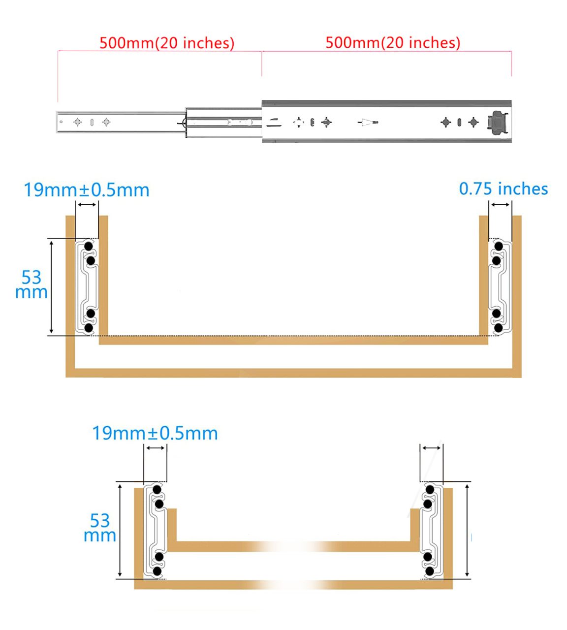
Put a mounting block or rails under that assembly and add support for the riggers and stretcher on the sliding bits and a drawer full of legal documents becomes a sliding rigger. Right? Keep it light if possible but very stiff. I’ve got a lot of capacity to work with, and it must accommodate the weight of the structure plus stresses as yet not well understood from the sculls.
Having settled on the sliding mechanism, the design that surrounds it offers a great many, clearer choices. Here are some potential cross-sections:
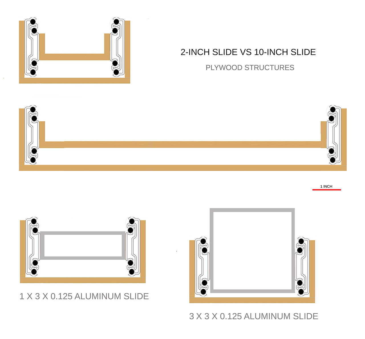
The outer “cabinet” offers several choices, too. For one thing, it does not have to be continuous. Stanchions rising up from the bottom of the boat from low thwarts spanning the keel at the points where the sliding mechanism needs to be fixed in place with a screw would do. It would be good if the underside of the slide were easy to clean, the bearings easy to lubricate. I like the aluminum versions for their potential rigidity and ease of working (the sliding beam would take threads, for instance, and bolts could be passed all the way through for attaching this and that, and if you screw it up, a replacement piece is easy to come by (a bit pricey perhaps, but easy to find).
Still thinking.
Day 34
I’ve been using Photoshop as an aid-de-design, a kind of ad-hoc CAD program by using layers to overlay decent scale drawings. I still like this design. For the accountant: MAS Epoxies refunded $240 in unneeded resin and hardener; Amazon wants $67 for the drawer slides. They’ll be here in two days, and I will start laying some things out to see which of several schemas looks most workable.
The exact length of this and that will depend on where screws must go to attach “drawer” and “cabinet” and that will be settled tomorrow when the slides arrive. Odds are the final parts list will include a 3-inch square aluminum tube (24 inches) and two 2-inch aluminum angles (24 inches each which will leave useful bits), some oak, some epoxy, a few threaded inserts, a handful of socket-cap screws and washers. If the “drawer” portion of the 3×3 tube can be as short as 17 inches, then I believe the remnant (7 inches) from a two-foot tube will be enough to lift the rigger clear of the splashbox. There are probably plenty of places to insure that 7 inches will be sufficient, but the difference between “plenty” and “barely” is the difference between “that was easy!” and “why didn’t that work?” so don’t balk if more metal is really needed.
Here’s an inscrutable diagram that probably documents some absurdities and unforeseen issues.
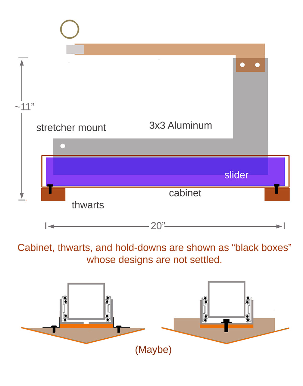
There are both thwarts and longitudinal pieces shown in the cross-sections of the not-quite-entirely-thought-through hold-downs. All in good time. After I transfer some of this from pixels to materials, things will be clearer. For better or worse.
Day 35
The slides are here, and they are heavy but also smooth and offer several mounting options for both “drawer” and “cabinet” attachments. Did I mention that they are heavy?
The metal stock I had in mind will suffice, with useful left-overs here and there. As of tonight, the following 24-inch pieces are on the way from Online Metals: 3-inch square aluminum tube, 0.125 inches, and two pieces of 2×2 aluminum angle stock, 0.1825 inches. The angle stock will comprise the “cabinet” and receive 1/4×20 socket head screws to hold the sliders in place. Brief experiments say that 10-32 screws will work to attach the “drawer.”
Now, consider the rigger itself.
RUM International sells a drop-in sliding rigger to which sculls are attached via a chromed steel tube. I do not say this pejoratively: it looks like a muffler shop could build one for me. This YouTube video showcases the sliding rig but also shows the tubular rigger.
All in all, today I like the molded high-density foam idea. Prefabbed riggers start just under $400 and rise effortlessly, gram by gram, into four figures. As with the slide, I think I can beat the retail numbers handily and learn something into the bargain.
Behold! I see an opportunity to play with a slide rule. Required: the volume of a plausible rigger in cubic feet (because that’s the unit of volume by which expanded polyurethane foam is described).

I based the calculations on the “Rowfit” plan shown below and got decently inside “slide rule accuracy,” but I messed up the conversion from cubic cm to cubic feet (how? don’t know). I struck that part out in the graphic after going over the numbers. Here’s the diagram from Rowfit’s order form with the corrected calculation. I’ve measured and relabeled some of the order form’s graphics:
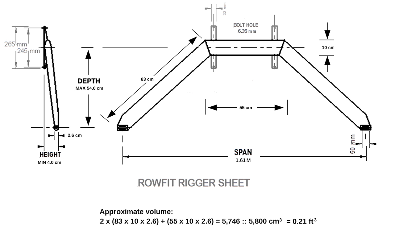
The spec sheet at Jamestown Distributors suggests that a quart of 6 lb foam recommended for structural applications will produce three times as much foam as needed for one rigger. I wouldn’t mind finding a smaller kit, but I foresee plenty of uses for any leftovers. Should I embed metal cores? I definitely should incorporate mounting hardware for mating the rigger to the vertical mast on the slide and for attaching oarlocks to the rigger. Version 1.0 is going to be an exercise in fiberglass and epoxy. Version 2, if any, might involve carbon (just for the experience) which I won’t invest in for an unproven schema. For now, just keep thinking.
Tomorrow
at last I hope to get off the computer and back into the shop. I’ve spent a lot of time working on the idea of the boat. Now it’s time to get back to work on the boat.