Take a deep breath and repeat this until you believe it: the rigger can be moved to wherever it needs to be moved. There is plenty of adaptability in the design. For example, new mounting threads can be placed in the “deck;” the mounting plates on the bottom of the slide can be relocated; the tube that attaches the riggers to the upright of the slider can be turned around, spacers added, etc. Everything depends on a solid platform upon which to mount the slide. Make that long enough, make sure there is space to mount the rig dead center left and right, make it level, and put it in the right ballpark fore and aft. Make it solid enough that it can host threaded inserts (and if it can’t, add some wood where needed).
As shown on the previous page, the line between the pins needs to be 6-8 inches forward of the aft edge of the seat. We know the range of positions where the seat may end up. So we know the extreme positions where the pins must be able to go. Cover that range, and stop worrying. Build the boat, and put it in the water. You can bring it home, dry it off, and reposition the slide, the seat, the riggers — all that can be done. But first, you have to build the boat.
Well. That took the rest of my structural epoxy. I have the finishing goop (MAS Traditional Maritime epoxy with 320 clear hardener) left and no more structural bits to build, so I guess that worked out, but I’m slightly shocked. Things got too busy to make photos along the way, so bear with me while I explain what I did.
I laid a bubble level across the splash box and set the boat on the proverbial even keel, propping it upright with metal scraps. Using 80-grit paper on the orbital sander, I scarfed the long edges of a 5×34 inch piece of 1/4-inch plywood. The thinned edges sit more stably in the bottom of the shallow v-hull and also make a more graceful fit. After dry-fitting the seat and rigger (more on that later), it was clear that I could just place this small deck piece as far aft it would go and worry about positioning hardware on it later. So I chiselled and sanded the aft end to fit around the base of the bulkhead and mounted it flush with that. Then I mixed up 100g of epoxy and hardener thickened with lots of wood flour. I poured the mix along about 30 inches of the v-hull. That was not even close to enough. I (quickly!) mixed up the rest of my low viscosity resin and fast hardener (about 300g in all), stirred in plenty of wood flour, and piled it onto the back of the “deck.” I drew some of the thickened epoxy over the scarfs. I pressed that into the bottom of the hull (nice fit) using a heavy metal beam for pressure, fiddled with its alignment just a bit, and then mostly just let it be. I applied the scrapings of the second mix as a fillet along one side of this “deck” and along some of the other side before I ran out. I’ll need to complete that fillet (and a few others) with finishing epoxy which I will also need to use to make the stretchers. It should be fine in those applications for which adhesion until the end of time is not the point.
When I say I’ve never seen one of these boats up close, I mean it.
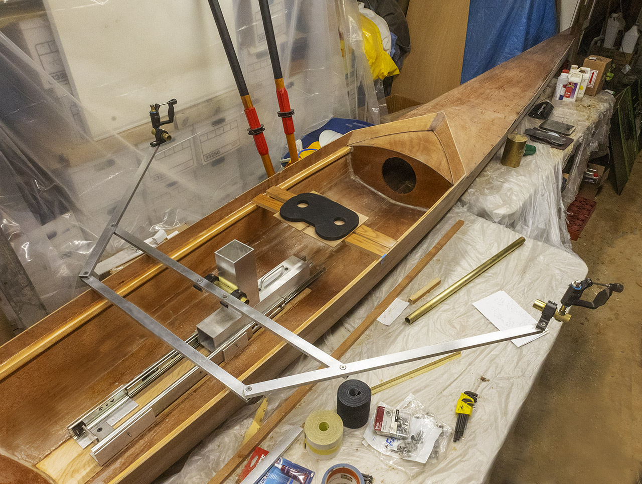
See those four bolts that hold the trapezoid in shape? Man, are they critical. I wanted the pins set very nearly the same distance outboard when the rigger is centered on the hull (sure, they’re adjustable, but with the adjustments set alike, symmetry would be good). A barely perceptible change in the angles defined by those bolts produces 3/4 to 1 or even 2 inches of change in the distance of each pin from the centerline. I am reasonably satisfied that the pins are set evenly after several interations. When I am really satisfied, I’ll epoxy the joints and apply LocTite to the bolts. Note that I moved the tube by which the rigger attaches to the upright to the other side of the longer bar and then moved the rigger to the other side of the upright. There was not nearly enough room between the rigger and the seat when near the catch, and now there is.
Nothing I’ve done so far reflects the recommended swivel height (see previous page) — the vertical distance from the swivel of the oarlocks to the top of the seat. That distance should be something like 5.5 – 7 inches. In the layout in the basement right now, it’s only 1 or 2 inches at most, so don’t sweat having room under the rigger for feet and legs; there will be. And don’t worry too much about raising the slide by 1/2 – 3/4 inch to accommodate the locking mechanism to hold the drop-in rigger in place: yes, it raises the CG of a heavy piece of gear, but the effect on overall CG is negligible considering that old lard butt with many times the mass is going to be sitting several inches higher no matter what. I can just fit the latch on the stern side of the slide and avoid elevating the entire mechanism, but I think I’d rather put the latch where I can keep an eye on it. Leave the space (if at all possible) for a future mod in case the incremental change in CG matters more than I think it will.
Day 76
Sometimes you just have to make a choice and run with what comes after. The slider will be mounted some fraction of an inch above the deck rather than directly to the deck. That simplifies more things than it complicates and will make it easier to correct inevitable mistakes. Tonight I did mostly invisible but nonetheless necessary things. For example, I locked the two sides of the slide together so it can be picked up and handled easily as a unit. Then I made a mess of the attachment for the hook by which the slider will be latched into the boat. S’OK, this is why almost everything attaches via some sort of adapter or mating piece: if (which is to say “when”) I mess those up, they’re easy and cheap to remake. The structure of the boat and its critical components are protected from my going off half-cocked or measuring too casually by almost disposable intermediate pieces.
Note to self: order some 10-32×1/2 bolts to replace the 3/4 ones in the slider now; it doesn’t sound like much of a change, but it will make attaching the stretchers simpler and it may help prevent some nasty pinches out on the water. (I know that makes no sense without pictures. Patience.)
Day 77
I’ve spent several hours making detailed sketches of just how the latching mechanism, the dovetails, the toggle clamp (not shown, but to the right of the forward dovetail below), and all will fit together. In my plans, everything depended on 3/8’s or 1/2-inch plywood for mounting points and to provide stand-off clearances here and there. Like this:
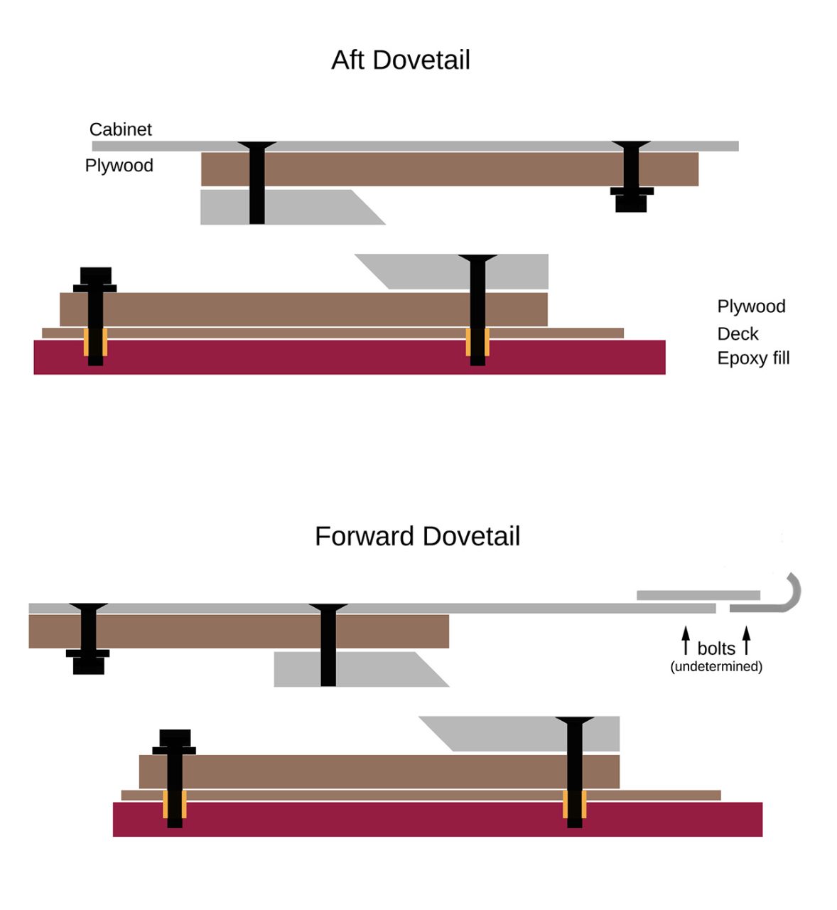
Then I found a stash of 3/4-inch plywood in the basement so I just started riffing and making it up on the fly (albeit with reference to these thoughts). Film at eleven. If it works:
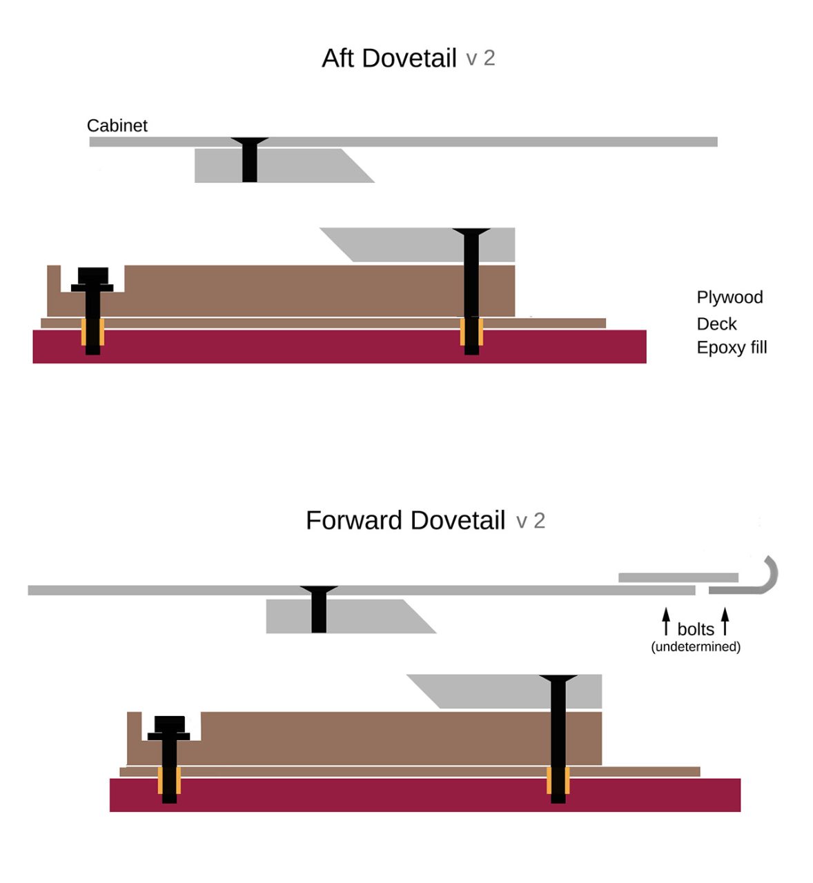
At least I got the wood blocks and the aluminum dovetail pieces cut and the hook shown at the right of both versions ready to go. (Hell, that’s more progress than I thought I’d made today.) Lots of drilling and countersinking were called for to let everything fit. The “undetermined” bolts turned out to be 1/4-20’s for which the 3/4-inch plywood spacer / adapter provided plenty of clearance. That said, I’m not drilling and tapping anything on the slider or the deck until my head is a little more settled.
Later that same night: YouTube and all kinds of advice says (1) threaded inserts in plywood are not a great idea, and (2) installing the inserts square to the wood is crucial and none of the recommended methods of insuring squareness will work now that the deck is installed (even if it were a good idea to place them in that thin wood). Several methods will work well in wood block(s) prior to installing in the boat. So here’s the plan: use some walnut I bought for Ophelia years ago (it won’t take much), and install inserts using the drill press. Make pilot holes and then use the press (unpowered) to at least start the inserts normal to the wood surface.
A still simpler notion:
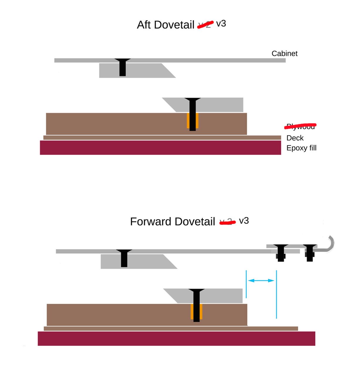
Maintain at least the clearance marked in blue in diagram “V3” so that the rigger can be set down with the dovetails some distance apart before being latched together. Some sort of bracket or bumper near the aft end of the deck or similar would make pre-launch fitting mindless. Some indication of proper lateral alignment might be handy, too.
Day 78
So, yes, basically that right there in the drawing is what I’ve spent all day working toward. It’s been a real Harry Potter sort of session in the boatyard (“When have any of our plans ever worked? We just show up and deal with it when we get there.”) The clearance I emphasized last night? It doesn’t exist. The “cabinet” piece up front is just too short. So I installed a third bit of aluminum L-beam specifically for the forward dovetail. I’m well on the way to encasing the whole damn “drawer” in a heavy aluminum frame, which is not the idea at all. And some of those pieces of aluminum don’t really tighten down all that well. I discovered that now that I am actually messing with the slide. J.B.Weld was already on the way for other reasons, but it will take care of that slack also.
Where things stand. All the screws are installed the right way around, countersunk where they need to be, tightened down well enough to convince me that it’s all going to work. I dry fit everything about the deck, the slider, the dovetails, then epoxied the small interior deck and the spacer that goes between that deck and the slider. No sooner than tomorrow I’ll install the mating dovetail halves to the block and fasten it down. [HA! HA! HA! laughed the cosmos. Dovetails are hard! Some mysterious and stubborn looseness or twist is present in the slide, and I think the rather casual dovetails are to blame.] If the toggle clamp still seems to fit as I have every reason to think it will, then I’ll get to work on fixing it in place, too. By Sunday, it should be possible to latch the slider into the boat and mean it. On Monday, I’ll replace six too-long screws with shorter ones and J.B.Weld what needs it. Then I can sweat placing the upright on the slider, attach the rigger, and, do some manner of temporary seat and stretcher mounts (temporary because I know those items will have to be moved, and until I know approximately where each belongs, there’s not much point in worrying about details). If all that goes as planned, then I can get on with final sanding of the hull and main decks (make a long board). Then seal everything. Varnish nothing until most or all the dimensions are set. As soon as a week from today, it could be ready for the water, but I probably won’t have worked out a way to transport it by then.
Big talk! The new “Traditional Marine Epoxy” and 320 clear hardener is very slow compared to LV/Fast combination I’d been using lately. Scary slow. As in, not hard (but at least not very tacky) after 4-5 hours at 66F. Stay tuned.
Time out for a little calculation. In a conventional sliding seat arrangement, each stroke includes raising the rower’s body 1/2 inch — the tracks for the sliding seat slope 1:20. The energy required for that elevation is about 20 joules. At a pace of 20 strokes per minute, with half of each stroke being used to raise 200 pounds, that’s about 20 joules expended over 1.5 seconds, or 13 watts. Some of that is returned in the recovery, minus losses to friction and flex. But the question arises: how much power is being used for something other than straight-ahead propulsion?
Concept2 provides a calculator for computing wattage required as a function of pace. It’s for erg machines on dry land, but since an entire industry is devoted to the notion that energy expended on the water is not radically different, I think it’s safe to start there:
watts = C/p^3
C is a constant, 2.80, and p is pace in seconds per meter. (For a good time, work out the units in which C is expressed.)
Consider a leisurely though klutzy cruise. 20 strokes per minute. Let’s say 9 minutes to row 2km. That’s 2000 meters in 540 seconds, or 0.27 s/m (p is the inverse of the more usual meters per second). The wattage required is 2.8/0.27^3 = 140 watts. (My assumed pace allows for a certain amount of thrashing about, because 20 strokes per minute ought to be faster than that.)
If the 13 watts used to raise the body were available to the stroke, then it’s easy to compute the speed difference that should make (reordering terms: pace is the cube root of 2.80/watts).
The sport is sufficiently mature that merely foregoing the slope of the sliding seat’s tracks cannot be expected to produce a faster boat — if it would, then tracks would not slope. The energy invested in the slope during the drive and withdrawn while moving toward the catch must map fairly directly to the energy expended in shoving the body back and forth. That, I think, is the point: the free(er) recovery movement is a respite in the midst of every stroke. The transfer of kinetic into potential energy effectively stores some of the effort from the back and quads to assist in the recovery. Most of that energy is available for propulsion in a boat with a sliding rigger (minus frictional losses and the energy required to move the rigger itself, which is roughly 10-15% of the mass of the rower’s body). Take a guess: assume that 70% of what would otherwise be expended in moving the rower’s lard to and fro, up and down, is available to be turned into go. Back to the Concept2 formulae:
140 watts will propel a shell at about 7.16 knots.
70% of about 13 watts is about 9 watts.
149 watts will propel the same boat at about 7.31 knots.
The difference is 11 seconds in a 2km race (which was more than enough for FISA to outlaw sliding riggers), or 56 seconds in a 10km head race or twilight cruise. More to the point, the same pace can be held with 9-10 watts less output which means more reserve for more distance, less sweat, or more strength remaining for getting the shell back to the car.