There are lots of options for mounting the slides to the cabinet. I think I will standardize on 10-32 machine screws. A single hex key will suffice for maintenance of the slider. I am taking care to avoid the need to cut or thread stainless steel: all the metal work is in aluminum (mostly 6061).
The rest of the metal for the slide will be here on Monday, and then we’ll see. Just stop thinking about that, and get back to making sawdust. But do keep thinking about the wing itself. Thus:
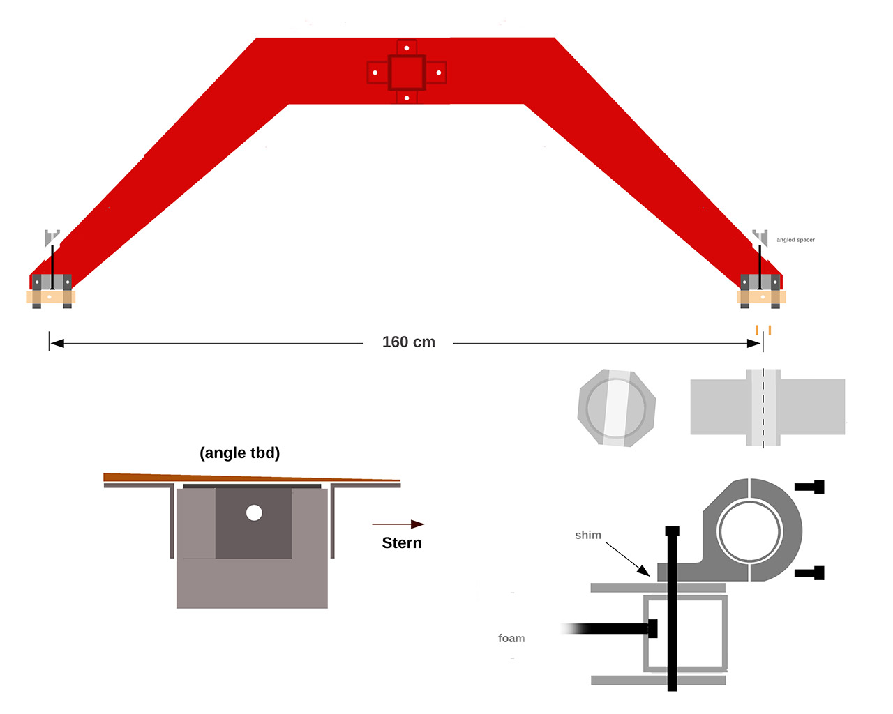
Much of that may be inscrutable without commentary, but I’m not talking until I’m pretty sure I have it thought out. (It’s a stern mounted sliding rigger and the rower is, as usual, proceeding backwards — is it any surprise that the label “bow” should be “stern” in the lower part of that sketch?)
The metal for the slider and the screws and the drill bit and the tap are here, also end caps for the 3-inch aluminum. It occurs to me that if I were to fill those segments with low-density foam (or just make sure they’re well sealed), they’d likely ensure that the entire sliding rigger assembly would float.
I’ve ordered another quart of epoxy, this time with fast hardener. The hardener on hand and the fast stuff can be mixed for custom cure times. Some of the next steps could benefit from faster cures, the better to iterate and adjust using multiple coats of epoxy and / or glass. And I do not want to be skimping on epoxy or making judgements skewed by excessive frugality.
The hex stock inside the rings provide inboard and outboard adjustability as well as fore and aft tilt adjustments. To allow inboard and outboard tilt, mount the two rings shown on one piece of metal and bolt it to aluminum inserts internal to the wing, possibly accessible through the upper or lower surface. Pairing the rings on mounting hardware that insures that the rings remain aligned. Then shim that common mounting plate as needed. [That‘s the key; see below for current overthinking.]
I’ve been hesitating to commit to cutting and drilling metal and to finalizing a few details about the hull (compartments perhaps? eventual hatches?). As for the rigger, I am concerned about rigidity. All the online commentary about riggers (and homebuilt sliding seats and sliding riggers especially) harp on flexure. Flex is bad. Flex absorbs energy that ought to go into propulsion. Flex wears things out, and flex breaks things. Most homebuilt riggers flex; on the other hand, few homebuilt mechanisms are metal, a passion for woodwork being more the norm. Still, I am thinking about how forces are transferred into the hull and I am loathe to commit to a design with shortcomings that should have been anticipated. Sooner or later, I’m just going to have to build something and start iterating in the altogether likely event that all is not satisfactory.
Day 37
The light bar clamps are here, and they are perfect. I have some suitable hex stock downstairs. Stay tuned for a sketch of how to attach all the hardware at the tips of the riggers — seems elegant right now, also simple, also cheap, but I haven’t actually drawn it to find the faults.
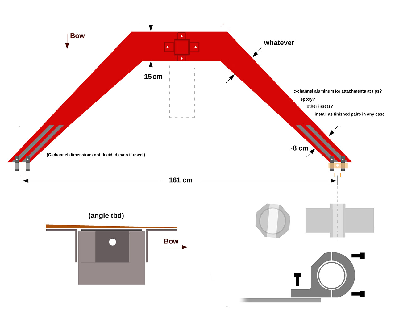
Here was once a labored discussion of using 1-inch square aluminum to build v1.0 that might be a finished rigger, or the core of a more finished rigger, or a prototype for subsequent versions… but you know what? I think the composite idea was the best one. Let’s do that. Here’s an updated and rethought plan drawing with proportions determined by the hardware in hand and by a similar rigger from Vespoli:
Now we get to consider whether high-density polyurethane foam in a mold is the way to go. Or maybe preformed blocks. Or balsa. And is there any reason to use carbon fiber while I’m at it? So many questions.
Day 38
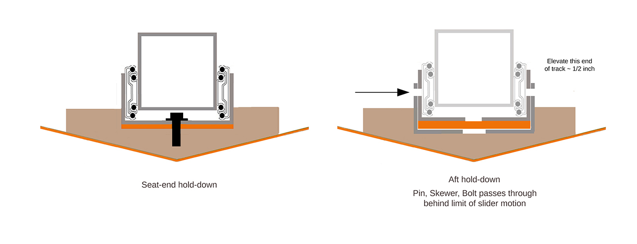
I carried the metal downstairs and set it beside the eventual “stateroom.” I also weighed each piece. The 3-inch aluminum tube, 24-inches long, weighs about 1.5kg as do the two 2-inch L pieces together. The drawer slides weigh 3.5kg together. The light-bar clamps to hold the oar-lock hardware come to 0.45kg not counting hex stock. It adds up. With everything in the boat, it does not feel “surprisingly light” which is my impression when the boat is empty. So I should surely aim for a drop-in sliding unit which dictates much about the floor plan. Sketches follow. The key is to join the L-pieces which comprise the cabinet with something flat (glassed plywood most likely) which fits between hull-mounted L pieces. Leave enough slack in the mid-ship hold-town to permit the rig to tilt slightly toward the seat: build in about a 1/2-inch drop somewhere, or provide for shimming to about that degree. Here’s a good start:
As for the rigger, I drafted the corners needed for a mold to produce the high-density foam. Positions are x,y in mm with the origin at the tip of the left outrigger:

This roughly follows the geometry of the Vespoli rigger shown above but with a broader crosspiece to allow it to play more easily with the massive upright by which it connects with the slider. I’ll need plywood for the mold base, planed oak flooring strips to outline the rigger, some kind of lid to constrain the foam, and some kind of release compound. Epoxy, fiberglass, and some paint. Or epoxy and carbon fiber (by the way, the term of art for wrapping something in carbon is “skinning”).
I’ve been gnawing on the attachment of the rigger to the upright column of the slide. All the sketches above show four mounting tabs on the side of the column. That is almost certainly not the way to go. I woke up this morning with a much simpler scheme in mind. (Keep reading. This is not the right way either, but I’m keeping it here just to document the design process.)
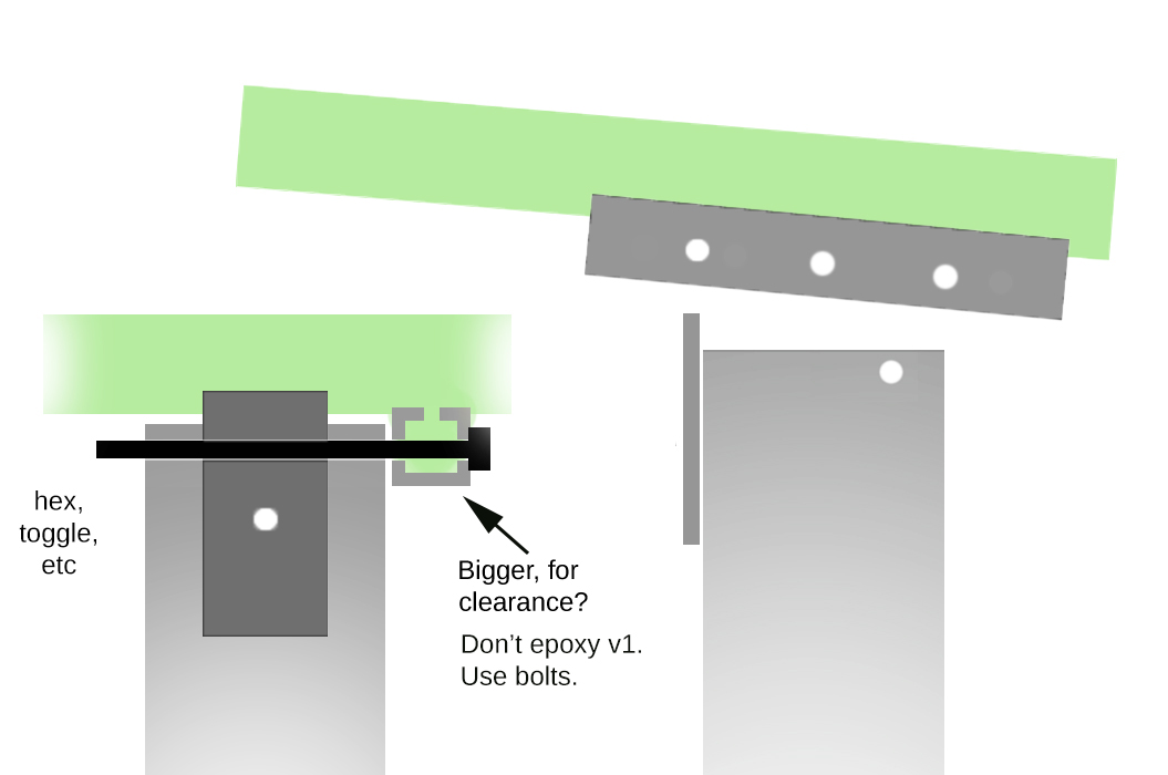
Green is the foam rigger. Embed or attach a 1-inch square tube placed so that the center of the rigger will be over the center of the upright column. Pass a bolt through everything and tighten it down (conceivably, this bolt and the one holding the sliding unit in place could be interchangeable). Note that there is no strain on the rigger. Put a brace on the front of the column, well padded at top, to provide a shim and support for the tilted rigger. Start with ordinary hex and socket hardware and after it proves out (or doesn’t) look for cam / ratchet / toggle bits to make assembly faster and tool free. Note the ease with which the rigger can be moved for and aft and the tilt adjusted with just a couple of new holes.
And yet…
It just looks — fiddly. I want things to go together without fiddling around so much. Try this:
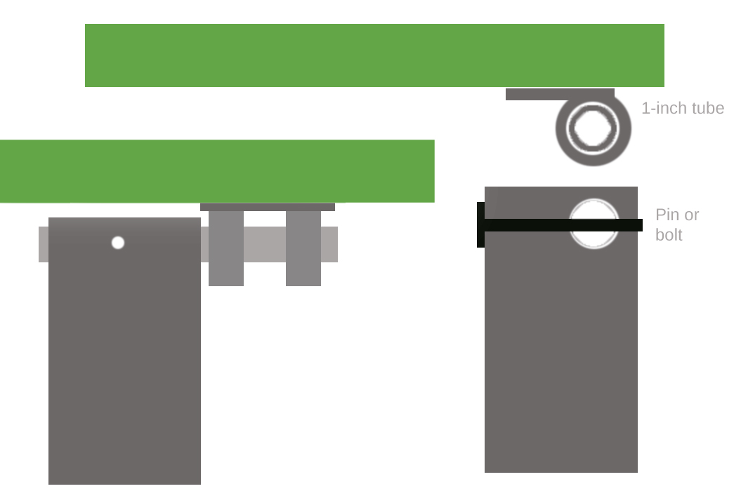
Green is, again, the foam rigger. Two light-bar clamps are attached to its lower surface. They grip a 1-inch tube. Could be aluminum. Could be stainless. Whatever. That tube passes through a hole in the top of the slider upright and is secured in place by a cotter pin or a bolt. Adjust the angle of the rigger by loosening the light-bar clamps and rotating the tube within; once it’s set, the retaining bolt insures that it won’t move or spin accidentally. Insert rubber spacers to keep it all from rattling. I like this one enough to have ordered the bit to cut that hole, cutting oil to make this and other aluminum work neat, and more light-bar clamps to make the rigger attachment (no pins, bolts, etc yet). And a couple of center punches to replace my missing one. File under avoiding mistakes owing to “excess frugality.”
I attacked the slider components with a micrometer and measured the available mounting points of both the “drawer” side and the “cabinet” side. There are only two imperatives, and they are not in serious conflict: keep the total mass down and maximize adjustability (because I don’t know jack about where everything is going to end up in the boat). For example, I want options to move the upright around on top of the “drawer” so I can adjust the wing for and aft without rebuilding all of Troy. The height required to clear the washbox is yet unknown, so don’t commit to a length for that upright yet.
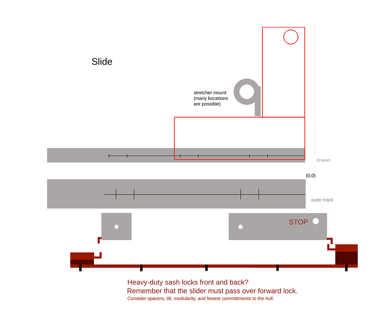
Here’s basically how it all fits into the boat (the proposed stretcher mount is overkill; use threaded inserts or just drill and tap some attachment points). Flood a shortish (21-24 inches) narrow strip (6-7 inches) along the keel line with thickened epoxy; let it form a flat floor. Lay a piece of glassed plywood on it with some threaded inserts ready to receive whatever is needed. Block the back of the inserts with cellophane tape before pressing the wood into the goop. Seal the edges. (Too much epoxy? Alternatively: build a low deck of similar size — oak strips? plywood? — with threaded inserts already installed, and epoxy it into place.) Either way, you can mount adapters, spacers, etc on the flat surface. As drawn: low spacers holding half of the components of sash locks to receive the sliding unit. Adjust tilt and position just by bolting down different hardware. If the sash lock idea is too cute, then screw it, literally: use shims and screws and worry about making it easier to work with later. [New search term: “Toggle Latch Clamp.” I bet we could make it work with a single latch at the midship end of the slider. Just get the adjustments right.] Note that what was the aft hold-down has been retained but turned into a padded stop for the slider — it is a part of the “cabinet” and has no attachment to the hull. The L-brackets have been trimmed down to free-standing brackets. They could be kept as continuous pieces: the stock is 24 inches; a continuous run of minimal length would be about 16 inches; what is shown involves about 8 inches of metal. That’s a substantial weight saving.
I have spent all damn day drawing, sketching, imagining schemes to do this, and I think it all comes down to the utility of that deck plate with inset threads. It seems very simple with that addition; suspiciously simple, actually. Keep thinking. Paranoia pays.
I am just about ready to cut, drill, and tap metal. Just about. I want a realistic idea about how it will all fit together, but there’s no need to sweat the finer details until I know the actual sliding mechanism works: this week with any luck.
Day 39
Actually, I don’t know what “day” it is. I’ve been busy on the computer here in virtual boatyard for several “Earth days.” After all this, here’s the slide I’ll be building in the physical shop [uhm, almost]:
The parts are shown exploded vertically at top and layered together at bottom to look for conflicts (I found a few and fixed them). The full-sized Photoshop documents for the slide and the rigger are scaled to yield measurements in cm; these JPEGs are sized for the web. Once I get started cutting, drilling, and tapping, this is going to need a new post. Detailed commentary can wait.
I’ll build the slide first and then do the rigger (because the rigger takes all new techniques, and enough is enough). The hull will need to be further along (the flat stateroon deck shown above and the splashbox will need to be in place, which means that the actual deck will need to be in place, too) in order to know exactly how tall the upright needs to be. Everything else can be tinkered together as opportunity and enthusiasm allow.
Day 40
That was almost the right idea. I awoke with notions. The toggle-clamp / ramp / lock-down needs to be done a little differently. Minor changes would make the drop-in installation more solid, easier to build, and easier to modify and refine. That’s a win-win-win. Then when I started to draw it to scale a further improvement seemed obvious. Both insights are shown in the drawing below.
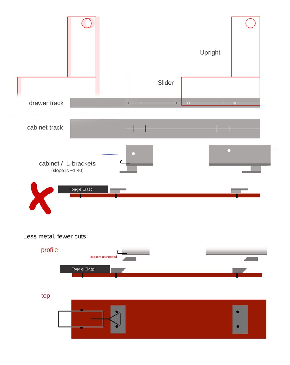
Thicknesses are not accurately represented in the base and mating pieces (the dovetails are in 1/4-inch 6061, and the red deck is 1/2 or 3/8-inch plywood). Metal is on the way. Details tk.
Day 41 (preview)
Metal is here, parts are lined up. The next post reflects where all this has led and what I mean to build.